How to reduce probe loading when using passive probes
In Part 1, a standard passive probe added up to 33% overshoot and inflated rise times by up to 50%. In Part 2, we test two simple changes at the probe tip and explain why they work: reducing tip capacitance and ground lead inductance in the measurement.
How to read the tracesKey findingsTip capacitanceGround lead inductancePassive probing checklistFAQ
Where we left off
In Part 1: Beware of probe loading artifacts with passive probes, we compared a clean reference signal against the same signal measured with a passive probe. The probe’s parasitic capacitance and inductance formed an RLC network with the circuit under test. The result was overshoot, undershoot, ringing and slower edges that did not exist in the real circuit.
The good news: you do not need a new probe to fix most of this. In this article, we change only how the probe touches the circuit.
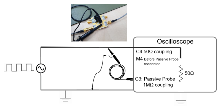
Test setup: Teledyne LeCroy HDO6054B oscilloscope (500 MHz, 12-bit, 10 GS/s), a standard passive probe, a simple test board with SMA connectors, and a 5 MHz signal from a signal generator.
Remove the sprung hook and the long ground lead
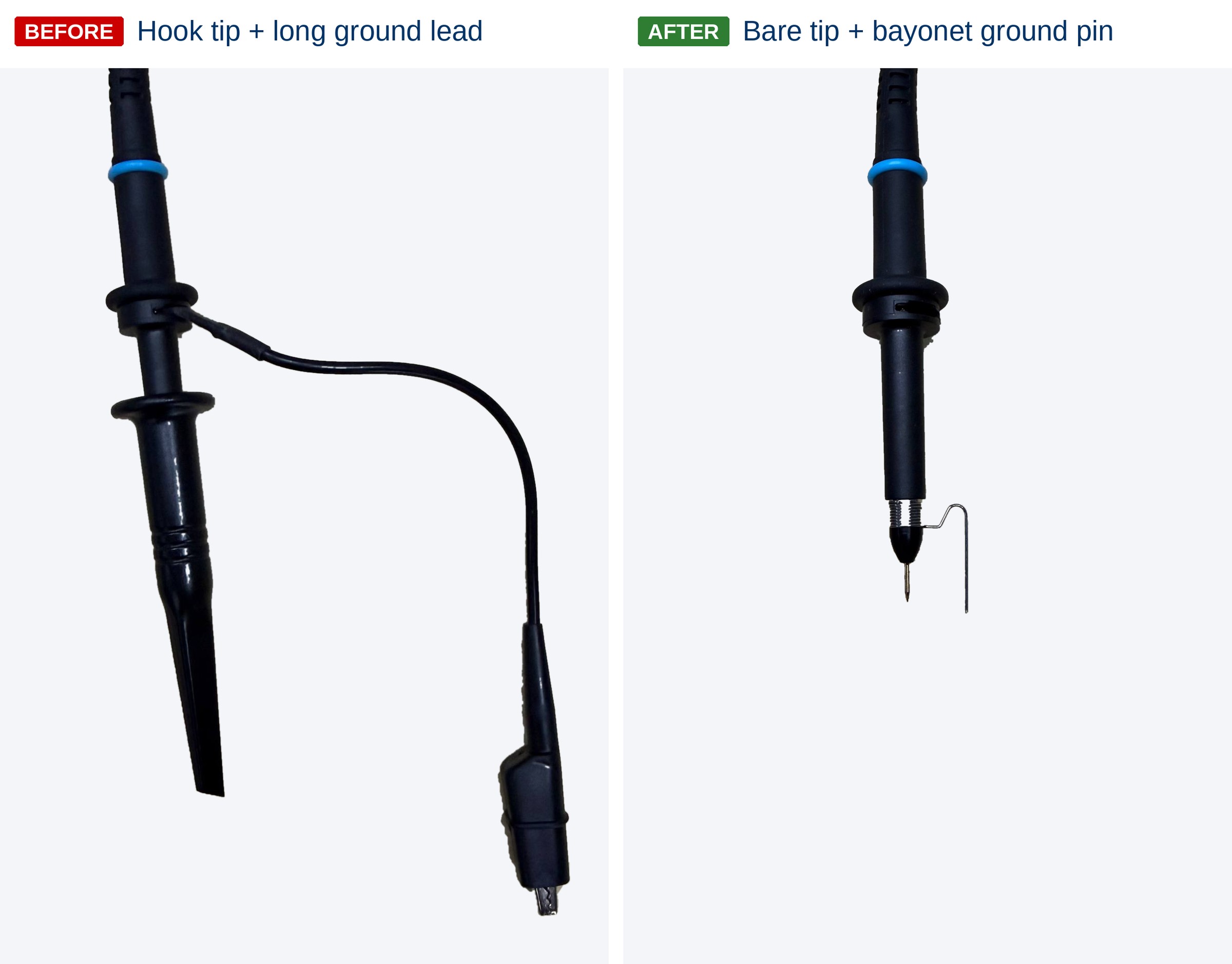
Fig 1: Left, the standard probe accessories. Right, sprung hook and ground lead removed, replaced with a ground spring.
On a passive probe, the sprung hook (the retractable hook that clips onto the tip) adds capacitance and the ground lead adds inductance. So the first approach is simply to take both away. The sprung hook comes off to expose the bare probe tip, and the long ground lead with crocodile clip is replaced by a short ground spring (sometimes called a bayonet ground pin) that clips onto the probe barrel.
You probably already have one. Most passive probes ship with a ground spring in the accessory kit, and many engineers never take it out of the bag.
With the ground spring, the probe tip touches the signal and the spring touches the nearest ground point, keeping the ground loop as small as possible (Fig 2).

Fig 2: Bare probe tip on the signal path, with the ground spring on the adjacent ground.
How to read the traces
All three traces show the same 5 MHz signal, captured in different ways:
Reference
Captured through coaxial cable straight into the oscilloscope at 50 Ω, with no probe attached.
The true signal, as clean as an oscilloscope can capture it.
Loaded circuit
Captured exactly the same way as the reference, but with the passive probe now touching the board.
Any difference from the reference is the probe disturbing your circuit.
Probe view
Captured through the passive probe itself, at the probing point. This is what you would normally see on screen.
Any difference from the reference is the probe misreporting your signal.
Loaded circuit vs Reference → does the probe change your circuit?
Probe view vs Reference → does the probe show you the truth?
What changed on the oscilloscope
With the sprung hook and long ground lead removed, all three traces now sit much closer together (Fig 3). All rise times below are measured from 20% to 80% of the edge.

Fig 3: Reference (M4): true signal with no probe attached. Loaded circuit (C4): the same signal with the probe touching the board. Probe view (C3): the waveform seen through the passive probe. Inset, left: zoom of the rising edge, with the arrow marking the small shelf on the loaded circuit caused by probe loading. Inset, right: for reference, the same edge with the sprung hook and long ground lead, from Fig 2 in Part 1.
Does the probe change my circuit? (Loaded circuit vs Reference)
Step distortion is much smaller
The loaded circuit now follows the reference closely for most of each edge.
A small shelf remains on each edge
Rise time is still about 1.05 ns vs 631 ps for the reference. The probe’s own capacitance is still loading the circuit.
Does the probe show the truth? (Probe view vs Reference)
Edges and amplitude are now accurate
Rise time 640 ps vs 631 ps (about 1.5%). Amplitude 561 mV vs 549 mV (about 2%).
Overshoot & ringing greatly reduced
Only slight residual ringing remains, mostly after the falling edge.
| With sprung hook + long ground lead (Part 1) | With ground spring (Part 2) | |
|---|---|---|
| Overshoot on the probe view | Up to 33% | Slight |
| Rise time error vs reference | Up to 50% | About 1.5% |
| Ringing | Prominent | Largely gone |
Table 1: How much the two changes improved the probe view. Each figure is measured against that test’s own reference.
Why is the probe view faster than the loaded circuit? It can look odd that the probe view (640 ps) is much closer to the reference than the loaded circuit (1,047 ps). The difference is where each trace is measured. The probe view sees the edge right at the probing point. The loaded circuit is measured at the oscilloscope’s 50 Ω input, after the edge has travelled past the probe’s capacitance, which slows it down along the way.
So why does such a small change at the probe tip make such a big difference? There are two separate mechanisms at work.
Tip capacitance causes the “step” on each edge

Fig 4: Parasitic capacitance at the probe tip draws charge from the circuit, causing a step-shaped distortion at the end of each edge. Circuit diagram adapted from Teledyne LeCroy, used with permission.
The sprung hook alone adds an estimated 5 pF of capacitance (EDN: Selecting oscilloscope passive probes). That sounds tiny, but capacitance stores charge, and that charge has to come from your circuit.
Using Q = C × V, a 5 pF tip at 1 V holds 5 pC of charge, roughly 31 million electrons. On a 5 V logic signal, that rises to 25 pC. Every time the signal switches, the circuit must charge or discharge this extra capacitance. That pulls on the voltage at the tail of each transition, producing the step-shaped distortion on the loaded circuit (Fig 4).
Removing the sprung hook takes away its share of the capacitance, but not all of it. The probe itself still has its own input capacitance, typically around 10 pF for a standard passive probe. That is why a smaller shelf still remains on the loaded circuit.
Ground lead inductance causes overshoot and ringing

Fig 5: Inductance in the ground lead couples with probe capacitance, forming an LC circuit with a characteristic resonant frequency (fres). Circuit diagrams adapted from Teledyne LeCroy (probe circuit, ground loop), used with permission.
The ground lead causes a different problem. Its inductance sits in series with the probe’s input capacitance, forming an LC circuit. A 6-inch ground lead with a crocodile clip typically carries around 150 to 200 nH of inductance. When a fast switching edge hits this LC circuit, it resonates at:
fres = 1 / (2π √(Lgnd × Cprobe))
With typical values of 150 nH ground lead inductance and 10 pF probe capacitance, the resonant frequency works out to roughly 130 MHz. A fast digital edge like ours carries significant energy up to the oscilloscope’s 500 MHz bandwidth, well above 130 MHz. So every edge excites this resonance, and the result is the overshoot and damped ringing seen in Part 1.
A ground spring is much shorter than a standard ground lead, so its inductance is a small fraction of the lead’s. That pushes the resonance much higher, above where most of the edge energy sits, and the ringing largely disappears.
A big improvement, with one limit
Removing the sprung hook and replacing the long ground lead with a ground spring made a standard passive probe far more trustworthy. The probe view now matches the reference to within about 2%, and the overshoot and ringing from Part 1 are largely gone.
The limit is the probe’s own input capacitance. It still loads the circuit slightly, which is why the loaded circuit keeps a small shelf on each edge. For most everyday measurements, that is acceptable. When it is not, for very fast edges or sensitive nodes, the next step is an active probe, with input capacitance typically 1 pF or less.
Passive probing checklist for cleaner waveforms
- Remove the sprung hook when measuring fast edges, and probe with the bare tip.
- Replace the long ground lead with a ground spring, grounded as close to the test point as possible. Check your probe’s accessory kit first.
- Compensate the probe to the oscilloscope channel before every critical measurement.
- Check probe bandwidth against rise time. The probe and oscilloscope together must comfortably cover the signal’s edge speed.
- Know when to step up. For very fast edges or sensitive nodes, an active probe is the better tool.
Frequently asked questions
What is probe loading?
Probe loading is the effect a probe’s own resistance, capacitance and inductance have on the circuit it measures. It can change both the real signal in the circuit and the waveform displayed on the oscilloscope. For a full explanation with test results, see Part 1: Beware of probe loading artifacts with passive probes.
Why does a long ground lead cause ringing on my oscilloscope?
The ground lead’s inductance forms an LC circuit with the probe’s capacitance. Fast edges excite this circuit at its resonant frequency, which shows up as overshoot and damped ringing that is not in the real signal.
How do I get rid of ringing on my oscilloscope?
Start at the probe tip. Remove the sprung hook, replace the long ground lead with a ground spring, and ground as close to the test point as possible. In our test, this brought the probe view to within about 2% of the reference signal. See the passive probing checklist above for more tips.
Do I need a better probe to fix overshoot and ringing?
Not always. In our test, removing the sprung hook and using a ground spring brought a standard passive probe to within about 2% of the reference signal. For faster signals or sensitive circuits, an active probe is the next step.
Speak to a Genetron T&M specialist about your measurement requirements.