Oscilloscope Voltage Probe Selection Guide: Types & Key Considerations such as probe loading, attenuation and more
Article by Wayne Lim (Credits to Ken Johnson and Jon Shechter from Teledyne LeCroy)
14 Aug 2025

Introduction to Oscilloscope Voltage Probes
When measuring voltages with an oscilloscope, the voltage probe you choose directly impacts accuracy, signal fidelity, and safety. Different oscilloscope voltage probe types—passive, active, differential, and specialised—are designed for specific applications. This guide explains the main categories, their strengths and trade-offs, and how to choose the right probe for your needs while minimising issues such as probe loading, which can affect signal integrity and measurement accuracy during testing.
Understanding Probe Loading and Why It Matters
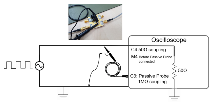
When an oscilloscope probe is connected to a circuit under test, it does not simply observe the signal passively. The probe itself becomes part of the circuit and introduces its own electrical characteristics into the measurement path. This interaction is known as probe loading, in which the probe’s impedance affects the behaviour of the signal being measured.
Because the probe adds both capacitance and resistance in parallel with the test point, it can alter waveform shape, amplitude, rise time, and overall signal fidelity. In low-frequency or low-impedance circuits, these effects may be minimal. However, in high-speed digital systems, RF applications, precision analogue circuits, or high-impedance designs, probe loading can significantly affect measurement accuracy and lead to misleading results.
Capacitive Probe Loading
Every oscilloscope probe has inherent input capacitance. Standard passive probes typically introduce between 8 pF and 20 pF of capacitance at the measurement point. When connected to a circuit, this capacitance forms a parallel capacitive load that can create a low-pass filtering effect, especially at higher frequencies.
As signal frequencies increase, capacitive loading may begin to attenuate high-frequency components, slow edge transitions, and distort waveform shapes. The impact becomes more pronounced when measuring circuits with higher source impedance, where even small amounts of added capacitance can affect signal integrity.
This is one reason why active probes are commonly used for high-speed measurements. Their significantly lower input capacitance, often below 1 pF, helps minimise loading effects and preserve waveform accuracy when capturing fast digital or RF signals. The interaction is commonly represented by the time-constant relationship τ = R × C, where R denotes the source impedance and C denotes the probe capacitance. As either value increases, signal degradation becomes increasingly noticeable at higher frequencies.
Resistive Probe Loading
In addition to capacitance, oscilloscope probes also introduce resistive loading into the circuit under test. A standard 10x passive probe typically presents an input impedance of approximately 10 MΩ in parallel with the oscilloscope’s own input impedance. For many general-purpose measurements, this resistive effect is relatively small and does not significantly alter circuit behaviour.
However, in high-impedance circuits such as sensor interfaces, precision analogue stages, MEMS devices, or sensitive measurement nodes, resistive loading can affect voltage levels and create measurable voltage-divider effects. This may result in inaccurate readings or altered operating conditions within the circuit itself.
Selecting probes with higher input impedance or using active probes can help reduce these effects in sensitive or high-impedance applications. Understanding both capacitive and resistive loading characteristics is therefore essential when choosing the appropriate probe for accurate oscilloscope measurements.
High Impedance, Single-Ended Passive Voltage Probes

Rugged, reliable, inexpensive, and ubiquitous—passive voltage probes are the default choice in most labs. With a typical input impedance of 10 MΩ, the resistive probe loading is minimized for general-purpose use. However, their bandwidth is lower than that of active probes, and capacitive probe loading can distort high-speed signals.
High Impedance, Single-Ended Active Voltage Probes

Active probes use internal amplification and buffering to achieve better bandwidth and lower capacitive probe loading compared to passive probes. These oscilloscope voltage probes deliver excellent signal integrity but typically support a lower voltage range and come at a higher cost.
Differential Oscilloscope Voltage Probes

Differential probes measure the voltage difference between two points rather than relative to ground. This allows isolated voltage measurements, making them ideal for floating circuits or high-side measurements.
Advantages: Electrical isolation, safe floating measurements, and the ability to reject unwanted common-mode signals.
Disadvantages: Higher cost and the need to consider parameters such as:
- Common Mode Voltage (Vcm) Range
- Differential Mode Voltage (Vdm) Range
- Common Mode Rejection Ratio (CMRR)
Low Voltage Differential Probes

Low voltage differential oscilloscope probes offer high bandwidth and excellent signal integrity, making them perfect for small, high-speed differential signals. However, they have limited Vcm and Vdm ratings, restricting their use to lower-voltage environments.
High Voltage Differential Probes

These oscilloscope voltage probes are built for very high Vcm and Vdm measurements, making them common in power electronics. They trade bandwidth for voltage capability, and higher attenuation can introduce more noise.
Specialized Oscilloscope Voltage Probes
- Optically Isolated Probes – e.g., Teledyne LeCroy HVFO108 and DL-ISO: Provide extreme isolation for fast high-voltage signals with minimal probe loading.
- Rail Probes – e.g., Teledyne LeCroy Active Voltage Rail Probe: Designed for low-voltage DC power rails, offering very low noise and high sensitivity.
- High Common Mode Probes – e.g., Teledyne LeCroy 60 V Common Mode Differential Probes: Handle high common-mode range with wide bandwidth for precision measurements.
How to Select the Right Oscilloscope Voltage Probe
1. Know Your DC Bus Voltage
- 60 Vdc (nominal)
- 170–1000 Vdc
- 1500 Vdc
- 6000 Vdc
2. Know Your Application
- Power semiconductor device testing
- Floating sensor measurements
- Discrete component measurements
- System inputs/outputs
3. Know Your Sub-Application
- Gate drive measurements (Vgs or Vge)
- Switching outputs (Vds or Vce)
4. Consider Semiconductor Material & Bandwidth
- Silicon (Si): ~100 MHz bandwidth
- Silicon Carbide (SiC): ~350 MHz bandwidth
- Gallium Nitride (GaN): ~1 GHz bandwidth
- Lower bandwidth may be sufficient for floating sensor or system I/O measurements
Frequently Asked Questions
What is probe loading in an oscilloscope measurement?
Probe loading refers to the effect an oscilloscope probe has on the circuit being measured. Because the probe adds its own resistance and capacitance to the measurement point, it can alter signal behaviour and affect waveform accuracy, especially in high-frequency or high-impedance circuits.
What is the difference between passive and active oscilloscope probes?
Passive probes use resistive and capacitive components to scale signals and are commonly used for general-purpose measurements. Active probes contain built-in active circuitry that provides lower input capacitance and higher input impedance, making them more suitable for high-speed digital, RF, and sensitive analogue measurements.
Why does probe capacitance matter in high-frequency measurements?
Probe capacitance can affect the accuracy with which high-frequency signals are captured. Higher capacitance introduces greater loading on the circuit, which may attenuate fast signal edges, distort waveforms, or reduce bandwidth during measurement.
When should a differential probe be used?
Differential probes are used when measuring signals that do not share a common ground reference with the oscilloscope. They are commonly required for floating measurements, power electronics, motor drives, and high-side voltage measurements where standard single-ended probes may create grounding or safety issues.
How do I choose the right oscilloscope voltage probe type?
The correct probe depends on factors such as signal frequency, voltage level, bandwidth requirements, source impedance, and grounding conditions. Passive probes are often sufficient for routine measurements, while active or differential probes may be necessary for high-speed, high-voltage, or precision applications.
Can the wrong oscilloscope probe affect measurement accuracy?
Yes. Using an unsuitable probe can introduce excessive loading, insufficient bandwidth, waveform distortion, or inaccurate voltage readings. Matching the probe’s electrical characteristics to the circuit under test helps ensure more reliable and representative measurements.
Conclusion
Selecting the right oscilloscope probe helps ensure more accurate and reliable measurements across different testing environments. Factors such as bandwidth, voltage range, input impedance, and probe loading all influence how a signal is captured and interpreted.
Different applications may require different probe types, including passive probes, differential probes, or a current probe for analysing current flow and power behaviour. Understanding these differences helps engineers select probe solutions that more closely match the electrical characteristics and performance requirements of the circuit under test.