Oscilloscope Models

Whether you require high bandwidth for fast signal analysis, advanced triggering capabilities for complex signal capture, or portability for on-the-go testing, The oscilloscopes that Genetron provides are the ideal choice for engineers and technicians seeking to enhance their test and measurement capabilities.

Precision and Performance: The Oscilloscope for High-Speed Testing

Designed for high-speed testing, our oscilloscope excels in applications that demand rapid signal capture and analysis. Its unparalleled performance allows engineers to accurately observe high-frequency signals and transient events, making it indispensable for tasks such as DDR memory testing and other high-speed serial data such as PCIe and USB up to the latest revision, HDMI or DP, to name a few. Be it validating the integrity of high-speed data lines or troubleshooting complex electronic systems, this oscilloscope provides the speed and precision necessary to ensure reliable results.
Filters

Find the Right Oscilloscope for Your Needs

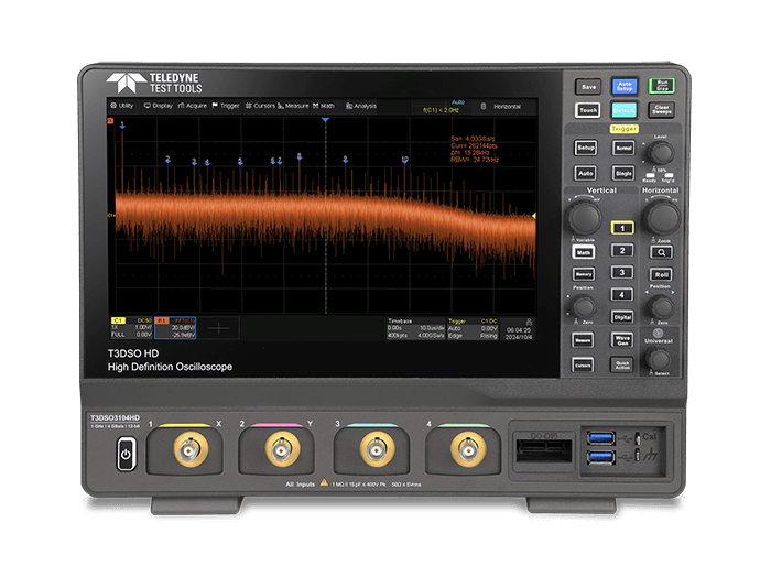
T3DSO3000HD, digital test and measurement equipment

T3DSO3000HD

The Teledyne Test Tools T3DSO3000HD series oscilloscopes deliver 12-bit resolution for precise signal analysis and are available in bandwidths ranging from 200 MHz to 1 GHz. With a maximum sampling rate of 4 GS/s, a deep memory depth of up to 400 Mpts/ch, and a waveform capture rate of up to 890,000 wfm/s in sequence mode, these oscilloscopes are equipped for advanced debugging. They include powerful features such as a 10.1” capacitive touch screen, serial protocol decoding, optional 16-channel mixed signal capability, and applications like Bode Plot and Power Analysis, making them ideal for engineers requiring high performance and versatility.

Bandwidth Selection:

200 MHz, 350 MHz, 500 MHz, 1 GHz

Resolution:

12 Bits

Sampling Rate:

4 GS/s (interleaving mode), 2 GS/s (non-interleaving mode)

Max Memory:

400 Mpts

Channels:

4

T3DSO2000HD, test and measurement oscilloscope

T3DSO2000HD

The Teledyne Test Tools T3DSO2000HD series oscilloscopes feature 12-bit resolution with bandwidths ranging from 100 MHz to 350 MHz, ensuring precise and low-noise signal measurements. They offer up to 2 GS/s sampling rate and 200 Mpts/ch memory depth, paired with advanced debugging tools like serial protocol decoding, Bode Plot, and Power Analysis. With a high waveform capture rate of up to 500,000 wfm/s, a 10.1” capacitive touch screen, and support for 16 digital channels, the T3DSO2000HD is ideal for comprehensive signal analysis in various applications, from R&D to production testing.

Bandwidth Selection:

100 MHz, 200 MHz, 350 MHz

Resolution:

12 Bits

Sampling Rate:

2 GS/s (interleaved), 1 GS/s (non-interleaved)

Max Memory:

200 Mpts

Channels:

4

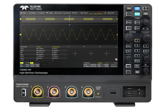
T3DSO1000HD, test and measurement equipment

T3DSO1000HD

The Teledyne Test Tools T3DSO1000HD Series Digital Oscilloscopes offer 12-bit resolution with bandwidth options of 100 MHz and 200 MHz, delivering high precision and low noise signal capture. Equipped with a waveform capture rate of up to 500,000 wfm/s, a 10.1” capacitive touch screen, and advanced features like serial decoding, Bode Plot, and Power Analysis, these oscilloscopes are ideal for comprehensive signal analysis and debugging. The series supports up to 4 analog channels, optional 16 digital channels, and advanced triggering, math, and measurement functions, making it versatile for a wide range of applications.

Bandwidth Selection:

100 MHz, 200 MHz

Resolution:

12 Bits

Sampling Rate:

2 GS/s (single channel), 1 GS/s (two channels), 500 MS/s (four channels).

Max Memory:

100 Mpts

Channels:

4

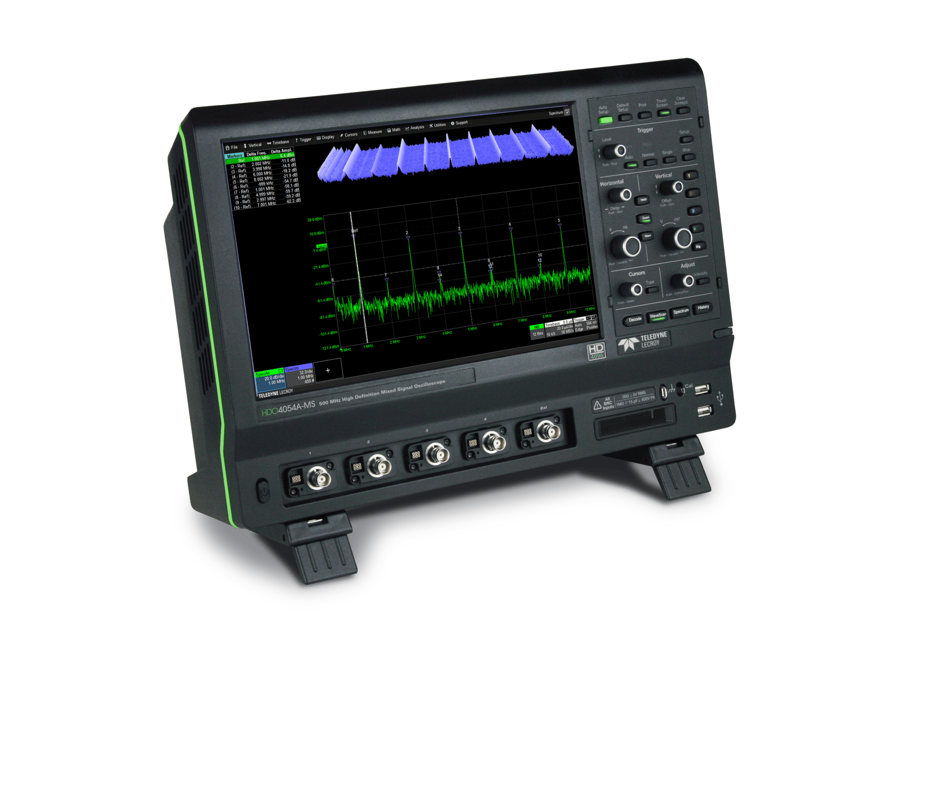
Teledyne LeCroy HDO4000A Oscilloscope

HDO4000A

The Teledyne LeCroy HDO4000A Oscilloscope delivers unmatched clarity and precision with its 12-bit HD4096 technology, offering 16 times the resolution of standard oscilloscopes. With bandwidth options up to 1 GHz and a sampling rate of 10 GS/s, it captures intricate waveform details with ease. Featuring 4 analog channels, deep memory up to 50 Mpts/channel, and optional mixed-signal capabilities with 16 digital inputs, it is ideal for debugging embedded systems, power integrity, and automotive electronics. Its intuitive MAUI interface on a 12.1” touchscreen streamlines complex tasks, making it a versatile tool for engineers across industries.

Bandwidth Selection:

200 MHz, 350 MHz, 500 MHz, 1 GHz

Resolution:

12 Bits

Sampling Rate:

10 GS/s

Max Memory:

50 Mpts

Channels:

4

waverunner8000hd-hvfo-tripod-setup_7047

WaveRunner 8000HD

The Teledyne LeCroy WaveRunner 8000HD Oscilloscope is designed for advanced multi-phase power analysis, offering 8 high-resolution input channels with 12-bit HD4096 technology and up to 2 GHz bandwidth. Its multi-channel capability makes it ideal for 3-phase power systems, enabling detailed analysis of voltage and current waveforms across all phases simultaneously. With a deep acquisition memory of up to 5 Gpts and extensive tools for protocol decoding and signal integrity analysis, these oscilloscopes provide engineers with the precision and flexibility needed for power electronics testing, embedded systems, and automotive applications. The intuitive MAUI interface ensures streamlined operation for complex diagnostics.

Bandwidth Selection:

350 MHz, 500 MHz, 1 GHz, 2 GHz

Resolution:

12 Bits

Sampling Rate:

10 GS/s

Max Memory:

5 Gpts

Channels:

8 to 16

waverunner9000-left-legsout-0049

WaveRunner 9000

The Teledyne LeCroy WaveRunner 9000 is a high-performance oscilloscopes series offering bandwidths ranging from 500 MHz to 4 GHz and a sampling rate of up to 40 GS/s. It is equipped with advanced signal analysis tools, exceptional serial data debugging capabilities, and compliance testing features, making it ideal for applications in embedded systems, automotive testing, and high-speed data communications. With its intuitive MAUI interface and OneTouch operation, the WaveRunner 9000 combines ease of use with powerful functionality, including extensive protocol analysis, jitter measurement, and waveform visualization. This series is designed to accelerate troubleshooting and optimize design workflows for engineers.

Bandwidth Selection:

500 MHz, 1 GHz, 2.5 GHz, 4 GHz

Resolution:

8 Bits

Sampling Rate:

Maximum of 40 GS/s

Max Memory:

128 Mpts

Channels:

4

LabMaster10Zi-A_100ghz_Right-DoubleMod_5896

LabMaster 10Zi-A

The Teledyne LeCroy LabMaster 10 Zi-A is a high-performance oscilloscope platform offering unparalleled bandwidths of up to 36 GHz and advanced multi-channel capabilities. It supports up to 80 synchronized channels, making it ideal for complex serial data and DDR memory test. Equipped with the powerful ChannelSync™ architecture, a 24-core server-class CPU, and up to 192 GB of RAM, the LabMaster 10 Zi-A delivers fast processing and precise analysis. Its advanced tools for jitter decomposition, eye diagram creation, and signal integrity analysis make it a leading choice for engineers in high-speed data communications, automotive, and semiconductor industries.

Bandwidth Selection:

20 GHz, 25 GHz, 30 GHz, 36 GHz

Resolution:

8 Bits

Sampling Rate:

80 GS/s

Max Memory:

512 Mpts

Channels:

4 to 80

wavepro-hd-embedded-6505

WavePro HD

The Teledyne LeCroy WavePro HD Oscilloscope combines high resolution and advanced features for precise signal analysis. Equipped with HD4096 technology, it delivers 12-bit resolution all the time, up to 8 GHz bandwidth, and 20 GS/s sampling rate. With an industry-leading acquisition memory of up to 5 Gpts, it allows detailed capture of long-duration signals. Its intuitive MAUI user interface, 15.6” full HD touchscreen, and extensive analysis toolsets make it ideal for debugging embedded systems, power integrity validation, and high-speed serial data testing. The WavePro HD is the ultimate solution for engineers demanding accuracy and reliability in complex system diagnostics.

Bandwidth Selection:

2.5 GHz, 4 GHz, 6 GHz, 8 GHz

Resolution:

12 Bits

Sampling Rate:

10 GS/s, 20 GS/s interleaved

Max Memory:

5 Gpts

Channels:

4

Types of Oscilloscopes

Understanding the different types of oscilloscopes is essential for selecting the right instrument for your application. Here are the primary categories:


1. Analog Oscilloscopes

Analog oscilloscopes display electrical signals directly onto a cathode-ray tube (CRT) screen. They are known for their real-time signal representation without the need for digitisation. However, they are using outdated technology, limited in bandwidth, and lack advanced features found in modern digital storage oscilloscopes.


2. Digital Storage Oscilloscopes (DSOs)

DSOs convert analog signals into digital data using an analog-to-digital converter (ADC). This digital data is stored in memory, allowing for complex signal processing, storage, and display. DSOs offer features like waveform storage, automated measurements, and advanced triggering, making them versatile for various applications.


3. Digital Sampling Oscilloscopes

These oscilloscopes are designed to capture very high-frequency signals by sampling at intervals longer than the signal period. They reconstruct the waveform using these samples, making them suitable for repetitive signals but not for single-shot events.


4. Mixed-Signal Oscilloscopes (MSOs)

MSOs combine the functionalities of DSOs with logic analyzers, allowing simultaneous analysis of analog and digital signals. This is particularly useful in debugging embedded systems where both types of signals coexist.


5. Mixed-Domain Oscilloscopes (MDOs)

MDOs integrate the features of DSOs with spectrum analyzers, enabling analysis in both time and frequency domains. This is beneficial for applications involving RF signals, providing a comprehensive view of signal behaviour.


6. Handheld Oscilloscopes

Portable and battery-powered, handheld oscilloscopes are ideal for field service applications. They offer basic functionalities suitable for on-site troubleshooting and maintenance tasks.


7. PC-Based Oscilloscopes

These oscilloscopes utilise a computer for signal processing and display, connecting via USB or other interfaces. They are cost-effective and leverage the computing power and display capabilities of PCs.


Each type of oscilloscope has its unique advantages and is suited to specific applications. Selecting the appropriate type depends on factors such as signal characteristics, analysis requirements, and environmental conditions.

Key Features of Our Oscilloscopes

High Bandwidth

Our oscilloscopes are equipped with high bandwidth capabilities, allowing for the capture and analysis of fast-changing signals with exceptional accuracy. This is crucial for engineers working on high-speed digital designs and RF applications, enabling them to observe fine details in their waveforms.

Advanced Triggering Options

With sophisticated triggering options, our oscilloscopes can isolate specific events in a complex signal. This feature allows users to capture elusive signals, making it easier to troubleshoot issues in designs such as DDR memory testing or high-speed serial communication, ultimately improving development efficiency.

Intuitive User Interface

Designed with user experience in mind, our oscilloscopes feature an intuitive interface that simplifies operation, even for complex measurements. Such ease of use helps engineers quickly set up tests and interpret results, reducing time spent on training and enhancing overall productivity.

Differences Between an Oscilloscope and Other Measurement Equipment

Oscilloscopes often complement other test and measurement tools, such as spectrum analyzers and logic analyzers, in various engineering applications. Here’s how they compare to other common tools:

1. Oscilloscopes vs. Spectrum Analyzers

  • Purpose: An oscilloscope displays how a signal varies over time by measuring its amplitude, making it ideal for time-domain analysis. Spectrum analyzers, on the other hand, focus on frequency-domain information by showing how signal energy is distributed across frequencies.
  • Displayed Information: Oscilloscopes provide time-related insights like rise and fall times, jitter, and phase shifts. Spectrum analyzers reveal frequency-related metrics such as signal bandwidth, carrier frequency, and harmonic content.
  • Applications: Engineers often buy oscilloscopes to visualise signal behaviour in real-time, such as for debugging circuits. Spectrum analyzers are indispensable for applications like radio frequency communication testing and electromagnetic interference analysis.


2. Oscilloscopes vs. Logic Analyzers

  • Signal Types: Mixed-signal oscilloscopes (MSOs) can measure both analog and digital signals, whereas logic analyzers are specifically designed to capture and analyse digital signals.
  • Channel Count: High-speed oscilloscopes typically support two to eight channels, making them ideal for smaller-scale debugging. Logic analyzers, in contrast, can handle dozens or even hundreds of digital signals simultaneously.
  • Analysis Features: Oscilloscopes offer advanced triggering options to capture intricate signal behaviours. Logic analyzers, while less complex in triggering, excel at analysing high-channel-count digital systems.


3. Mixed-Domain Oscilloscopes
Some high-speed oscilloscopes combine time-domain and frequency-domain capabilities, such as incorporating fast Fourier transform (FFT) functionality. These mixed-domain oscilloscopes allow engineers to perform both DDR memory test analysis and spectrum analysis using a single device.

In short, oscilloscopes, spectrum analyzers, and logic analyzers are complementary tools, each offering unique insights depending on the analysis required. By understanding their differences, engineers can choose the right combination of equipment for their specific needs.

Key Considerations for Choosing the Right Oscilloscope

Selecting the best oscilloscope requires evaluating several critical factors to ensure it aligns with your testing needs.


1. Bandwidth Requirements

The oscilloscope’s bandwidth determines its ability to accurately capture high-frequency signals. For applications like DDR memory tests, where signal integrity at high speeds is critical, a higher bandwidth oscilloscope is essential. As a rule of thumb, choose an oscilloscope with a bandwidth at least five times higher than the highest frequency component of your signal to ensure accurate representation.


2. Sampling Rate

The sampling rate dictates how frequently the oscilloscope samples the input signal per second. A higher sampling rate provides a more detailed representation of the waveform, which is vital for capturing rapid transient events. For accurate signal reconstruction, select an oscilloscope with a sampling rate at least 10 times the signal’s highest frequency, adhering to the Nyquist theorem.


3. Resolution and Accuracy

Resolution refers to the oscilloscope’s ability to distinguish between small voltage differences. Oscilloscopes with pure 12-bits hardware ADC offer 16 times more precise measurements than traditional 8-bits oscilloscopes. This is particularly important when analysing low-amplitude signals or when signal fidelity is paramount.


4. Memory Depth

Memory depth determines how much data the oscilloscope can store during a single acquisition. A deeper memory allows for longer signal captures at high sampling rates, enabling detailed analysis of complex signals over extended periods. This is especially beneficial when performing DDR memory tests, where capturing long data streams is necessary to assess performance accurately.


5. Number of Channels

The number of channels dictates how many signals can be simultaneously monitored. For comprehensive analysis of multi-signal systems, such as embedded systems or multi-lane serial data streams, oscilloscopes with four or more channels are advantageous. This capability allows for simultaneous observation of multiple test points, facilitating efficient debugging and analysis.


6. Triggering and Decoding Capabilities

Advanced triggering options enable the oscilloscope to isolate specific events within a complex signal, aiding in the identification of anomalies. Decoding capabilities for protocols like I²C, SPI, or UART are invaluable for embedded system development, allowing for real-time analysis of communication buses.


7. Form Factor and Portability

Depending on the application environment, the oscilloscope’s form factor may be a consideration. Benchtop oscilloscopes offer extensive features suitable for laboratory settings, while portable or handheld oscilloscopes are ideal for fieldwork due to their compact size and battery operation.


8. User Interface and Connectivity

An intuitive user interface enhances productivity by simplifying instrument operation. Touchscreen interfaces, customisable displays, and easy access to functions can significantly improve the user experience. Additionally, connectivity options such as USB, LAN, or GPIB facilitate data transfer, remote control, and integration into automated test setups, streamlining workflows.


9. Budget Constraints

While it’s important to select an oscilloscope that meets technical requirements, budget considerations cannot be overlooked. Assess the cost-to-benefit ratio, ensuring that the chosen instrument provides the necessary features without unnecessary expenditures. Entry-level oscilloscopes may suffice for basic applications, whereas advanced models with higher specifications are justified for complex analyses.


By carefully evaluating these factors, professionals can make informed decisions when selecting an oscilloscope, ensuring it meets the demands of their specific applications and contributes to efficient and accurate testing processes.


Using an Oscilloscope for DDR Memory Testing

Performing a DDR memory test requires an oscilloscope with specific capabilities to accurately capture and analyse high-speed signals. Here’s a step-by-step guide:​

  • Select an Appropriate Oscilloscope

    • Bandwidth: Ensure the oscilloscope’s bandwidth is sufficient to capture the highest frequency components of the DDR signals. Since DDR signals can vary in transfer rates even within the same generation, selecting the appropriate oscilloscope bandwidth for DDR memory testing requires careful consideration.
    • Sampling Rate: A higher sampling rate provides better resolution. Aim for a sampling rate at least twice the oscilloscope’s bandwidth.​
    • Memory Depth: Adequate memory depth allows for capturing longer data records without sacrificing resolution, essential for observing DDR burst patterns.​
  • Configure Probing

    • Differential Probes: Use high-quality differential probes with minimal loading effect to accurately capture the DDR signals without distorting them.​
    • Probe Placement: For DDR memory testing, users may opt to use interposers for a cleaner, reusable, and more consistent probing setup. Alternatively, direct soldering onto exposed signal points—such as BGA balls or PCB pads—can be used when interposers are not suitable or available.
  • Set Up the Oscilloscope

    • Triggering: Configure the oscilloscope to trigger on specific DDR events, such as read or write commands, to isolate the desired signal segments.​
    • Time Base and Scale: Adjust the time base and vertical scale to appropriately display the DDR signal characteristics.​
    • Read / Write separation: At higher DDR speeds, the timing margin for detecting skew between DQ and DQS becomes increasingly narrow due to rapid signal transitions. To ensure accurate identification of read and write bursts, it is recommended to complement the oscilloscope with a high-speed digital analyzer. By capturing the command/address (CA) bus, the analyzer enables precise burst direction decoding, eliminating ambiguity in read/write separation.
  • Perform Signal Integrity Analysis

    • Eye Diagrams: Generate eye diagrams to assess the quality of the DDR signals, checking for timing jitter, noise margins, and signal integrity issues.​
    • Timing Analysis: Measure setup and hold times to ensure they meet DDR specifications.​
  • Compliance Testing

    • Utilise the oscilloscope’s compliance testing software to automatically verify that the DDR signals adhere to industry standards and specifications.​

Frequently Asked Questions

What challenges are associated with DDR memory testing?

DDR memory testing involves challenges such as high-speed signal integrity issues, precise timing requirements, and susceptibility to noise and crosstalk, necessitating advanced testing equipment and methodologies.​

How does signal integrity affect DDR memory performance?

Poor signal integrity can lead to data errors, timing violations, and system instability in DDR memory modules, impacting overall performance and reliability.​

What role does jitter play in DDR memory testing?

Jitter refers to timing variations in signal transitions. Excessive jitter in DDR memory signals can cause setup and hold time violations, leading to data corruption.​

How can oscilloscopes assist in DDR memory compliance testing?

Oscilloscopes equipped with compliance testing software can automatically verify DDR memory signals against industry standards, simplifying the validation process and ensuring adherence to specifications.